


1/7 Scale Blackburn Buccaneer All Composite Scratch Build


 10-23-2018, 05:32 PM
#53

My Feedback: (20)
Paul,
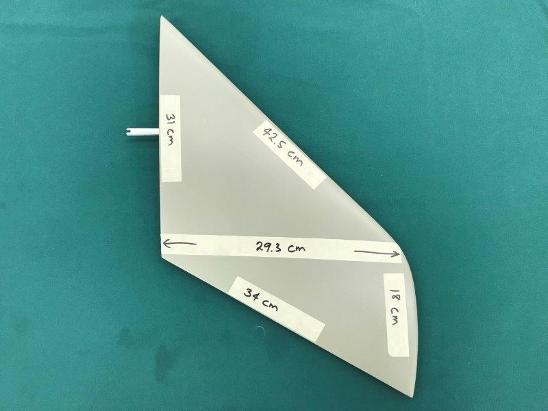
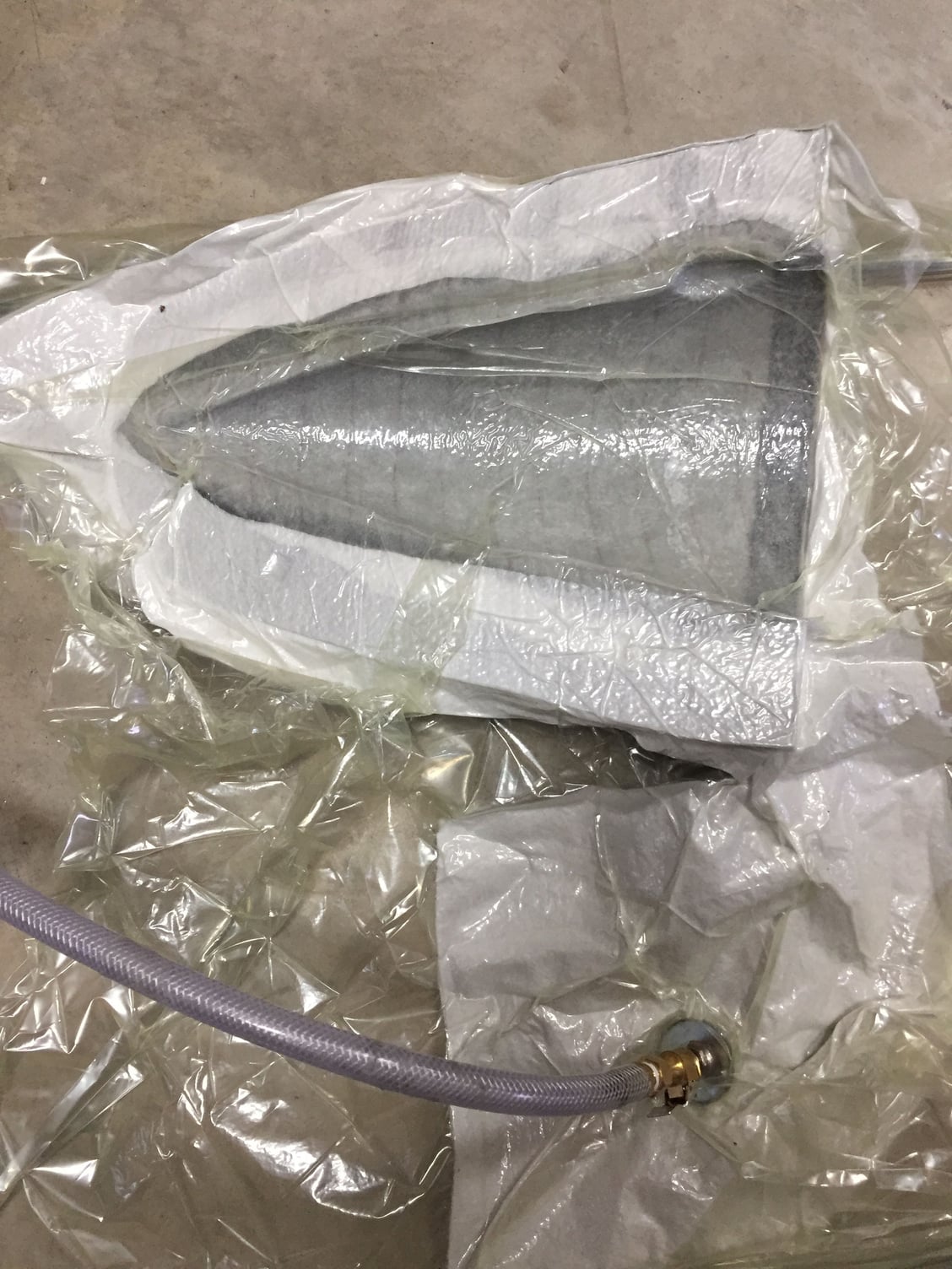
Here is a photo I took a couple of months ago when starting to think about the stab issues. Its approximate. The problems are, pivot point in wrong place, poor airfoil, inadequate pivot pin size and material, and unusable stab actuating mechanism. My current solution is to scrap the supplied stabs and mounts and start over with a new stab and mounting design. That's as far as I have gone on it. It will require making new stabs with a good airfoil and a new mounting solution. I want the stabs to be removable for transportation.
Thanks, Gary
10-24-2018, 09:54 AM
#54

I have to make stabs for a skymaster f-5 too, so I will be interested to see how you guys go.
I was thinking blue foam cut from spyderfoam, with a couple of ribs on the pivot shaft, cross drilled and pinned at each rib. But I would rather copy someone else!!
I was thinking blue foam cut from spyderfoam, with a couple of ribs on the pivot shaft, cross drilled and pinned at each rib. But I would rather copy someone else!!
10-24-2018, 04:24 PM
#55
My Feedback: (20)
I don't want to clutter up Paul's Buccaneer thread with F-105 stab stuff but I would love to discuss ideas with you guys. I will re-post my photo above on the F-105 thread and further discuss there.
Paul you are showing me lots of good stuff on the Buccaneer here so please keep it going. I am amazed at your ability to use CAD, 3D print, and laser cut technology to get the Buccaneer from idea to reality.
Gary
Paul you are showing me lots of good stuff on the Buccaneer here so please keep it going. I am amazed at your ability to use CAD, 3D print, and laser cut technology to get the Buccaneer from idea to reality.
Gary
10-24-2018, 06:24 PM
#56
Back to the Buccaneer.
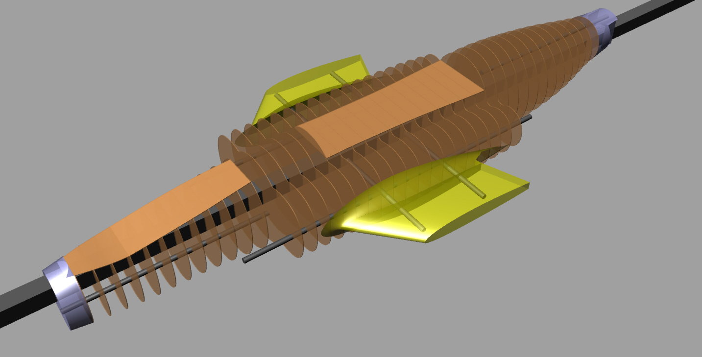
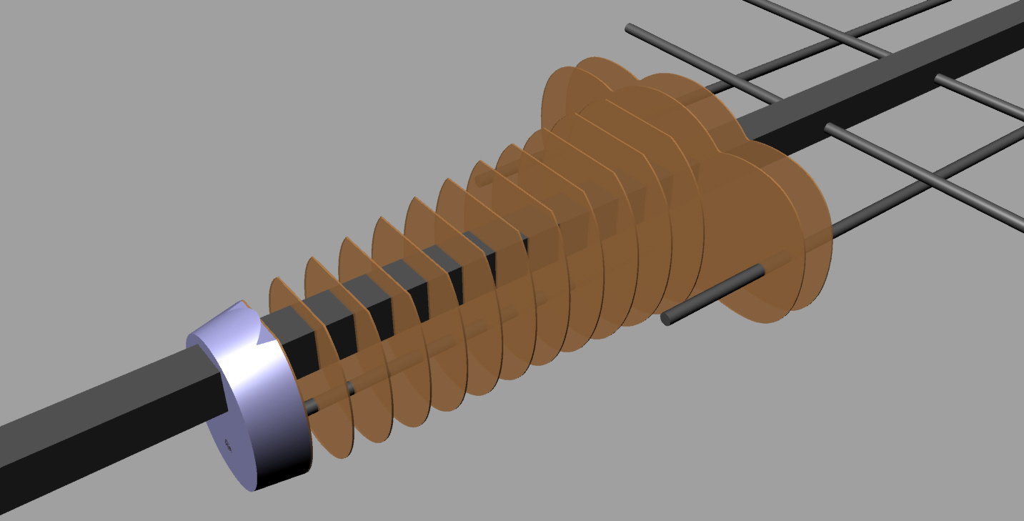
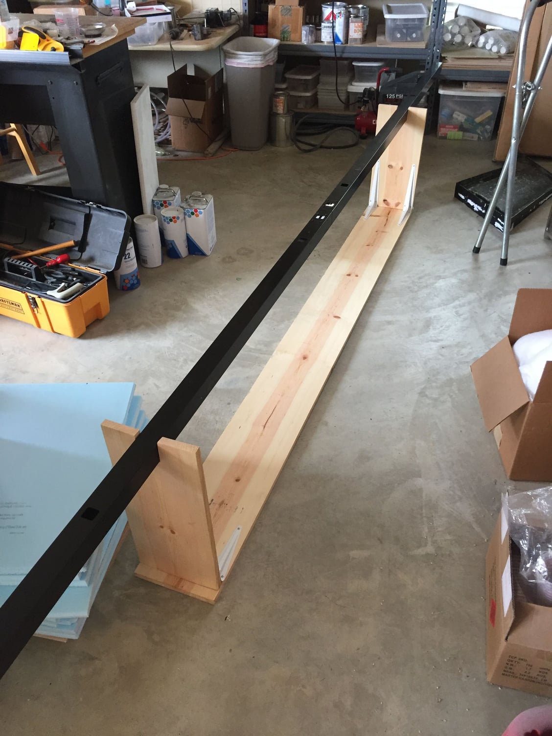
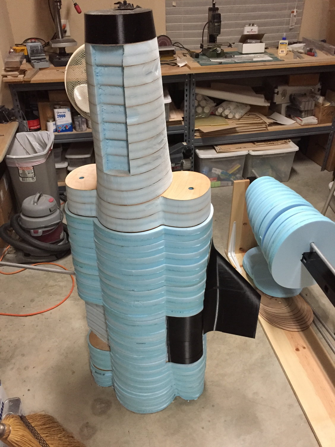
With the CAD model of the fuselage complete, I could start on the plug construction. My plan was to build thin bulkhead cross section templates and fill out between the sections with sheets of blue foam. The fuselage plug was going to be assembled on a 2" square metal fence-post as a structural member, with additional 3/8" tubes to act as alignment guides. A wooden support fixture was built to hold the entire fuselage at any angle for ease of working on it.
The inner wings where they blend into the fuselage, along with the forward and aft sections were to be 3D printed.
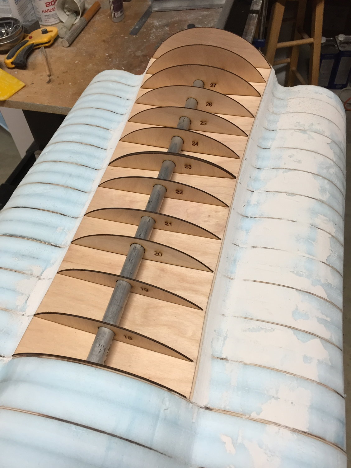
After measuring a stack of 1/16 ply and blue foam to get the correct spacing, I sectioned the CAD model and produced a series of ply bulkheads, nearly 50 in total. These were laser cut, including the holes for the support and guide tubes.
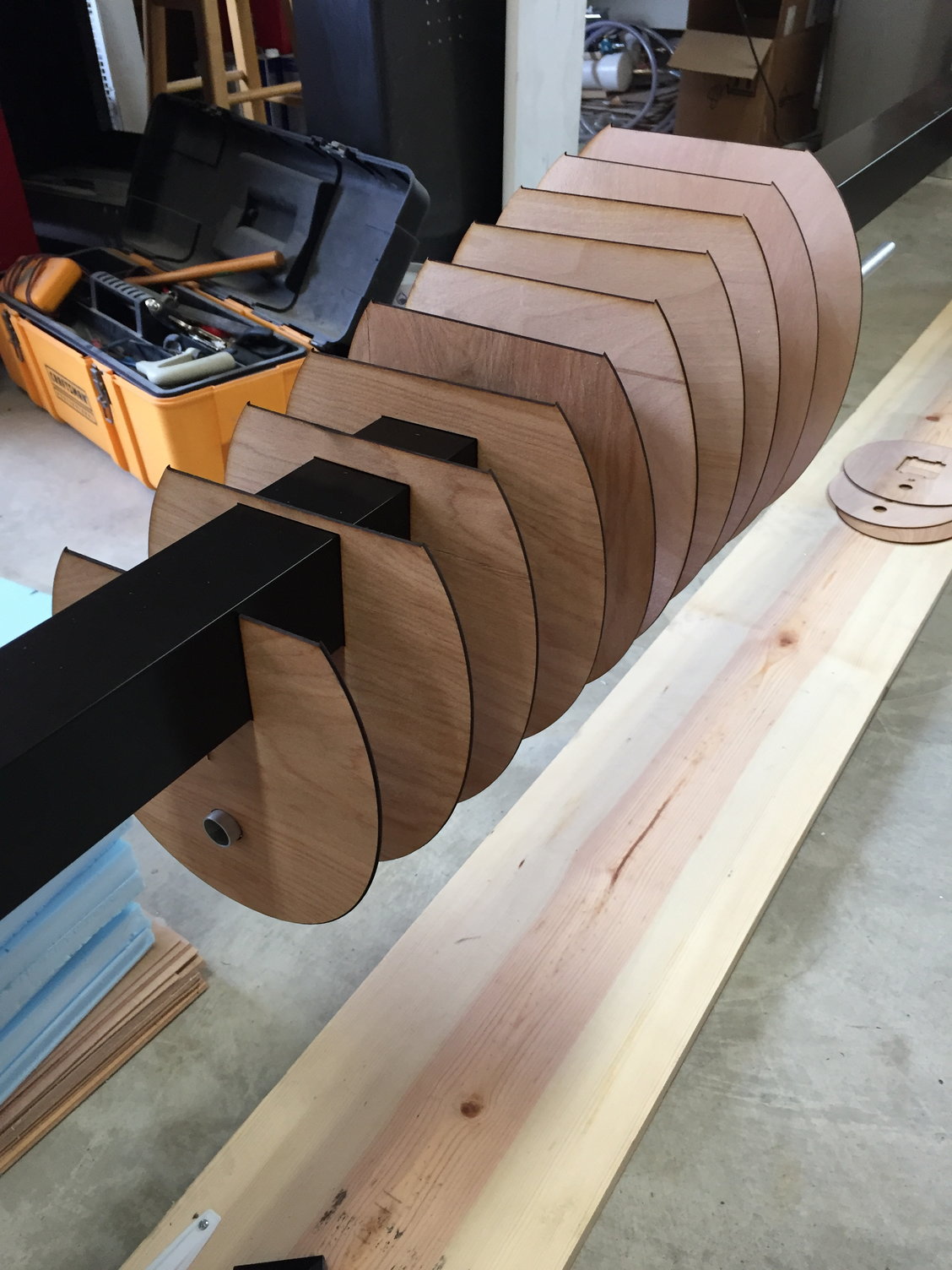
With the CAD model of the fuselage complete, I could start on the plug construction. My plan was to build thin bulkhead cross section templates and fill out between the sections with sheets of blue foam. The fuselage plug was going to be assembled on a 2" square metal fence-post as a structural member, with additional 3/8" tubes to act as alignment guides. A wooden support fixture was built to hold the entire fuselage at any angle for ease of working on it.
The inner wings where they blend into the fuselage, along with the forward and aft sections were to be 3D printed.
After measuring a stack of 1/16 ply and blue foam to get the correct spacing, I sectioned the CAD model and produced a series of ply bulkheads, nearly 50 in total. These were laser cut, including the holes for the support and guide tubes.
10-24-2018, 06:35 PM
#57
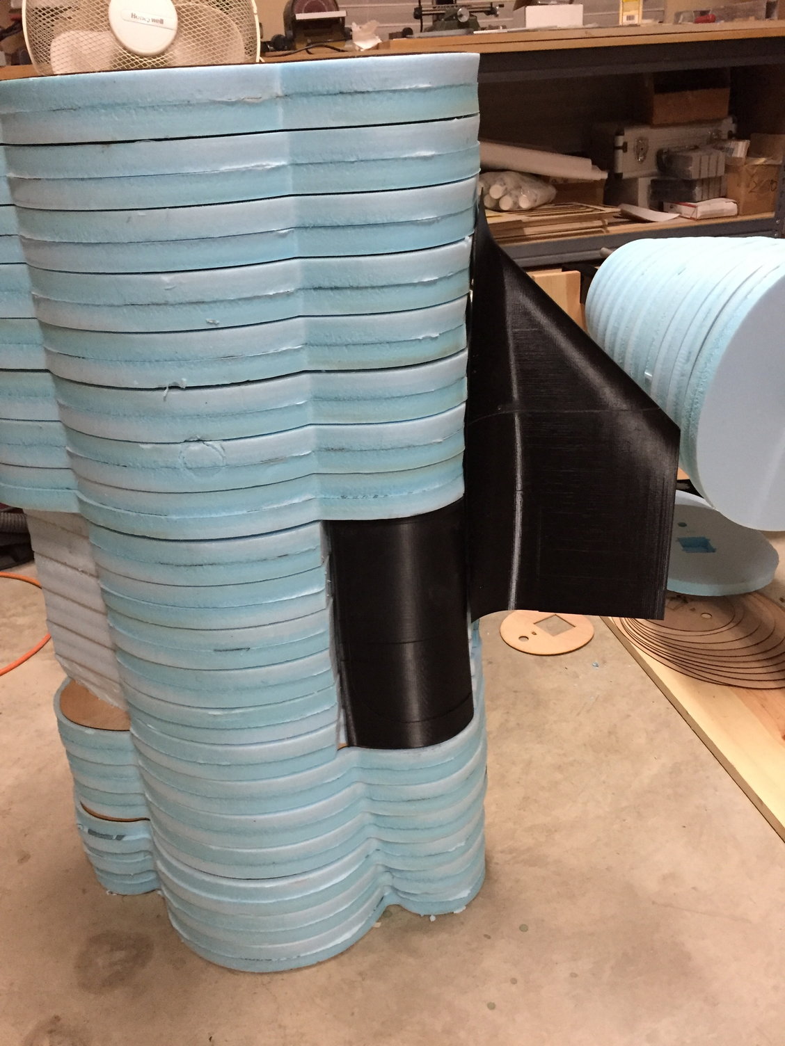
The 3/4" blue foam sheets were laser cut 10mm oversize due to the uneven edge induced by the laser cutter. 2 foam sheets were used between each ply bulkhead.
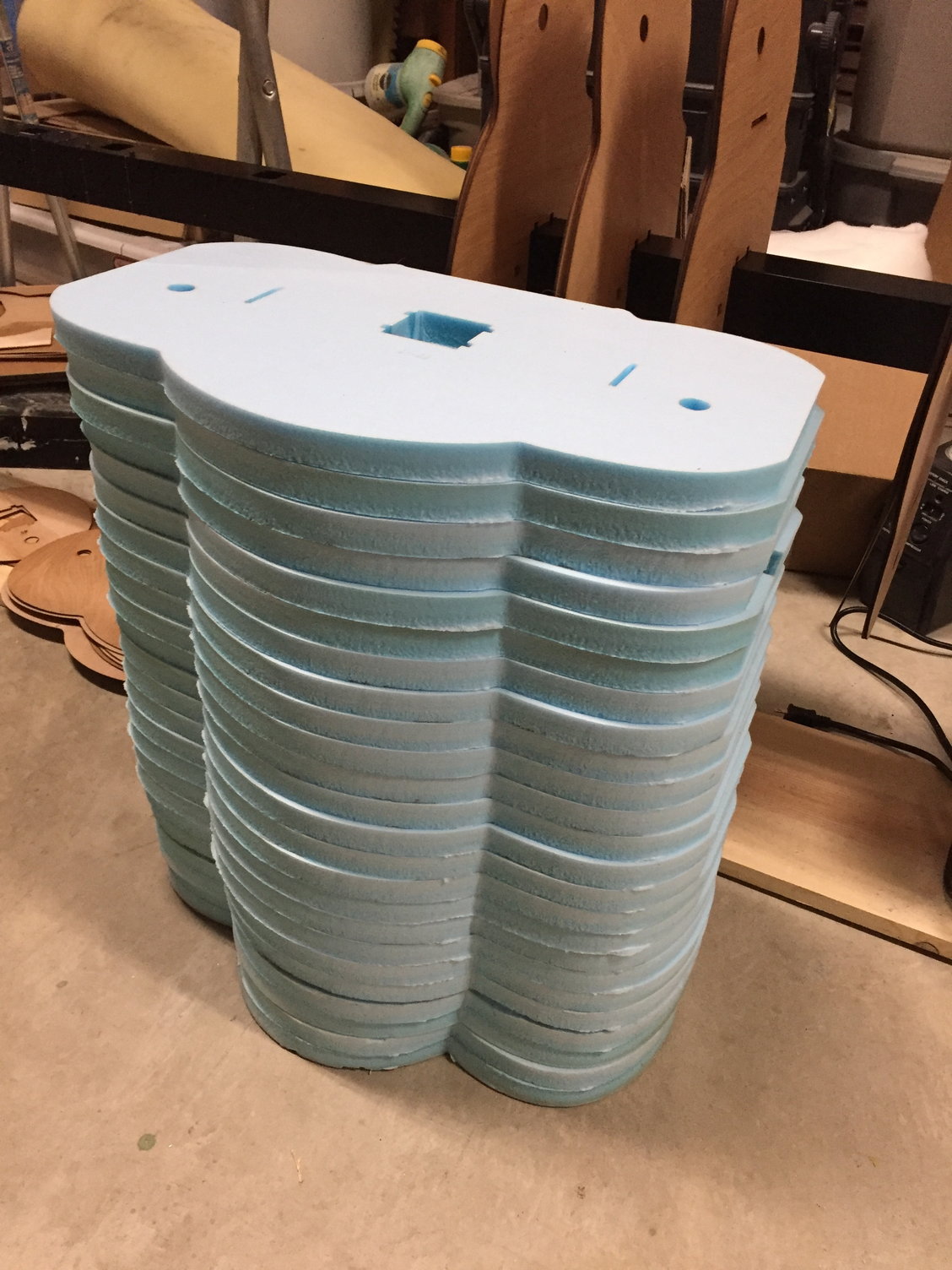

The sandwich was then bonded together in sections using 3M 77 spay adhesive. I initially used spay Gorilla Glue, but it dissolved the foam and did not bond well. 3M 77 worked well.Up until this point I hadn't decided on how many pieces I woudl section the fuselage into, either a single giant piece, or a couple of more manageable sections. As I started to build up the plug I settled on a 3 piece fuselage plug concept, forward fuselage to just behind the intakes, center body to just aft of the exhausts ans then a final rear section.
The sandwich was then bonded together in sections using 3M 77 spay adhesive. I initially used spay Gorilla Glue, but it dissolved the foam and did not bond well. 3M 77 worked well.Up until this point I hadn't decided on how many pieces I woudl section the fuselage into, either a single giant piece, or a couple of more manageable sections. As I started to build up the plug I settled on a 3 piece fuselage plug concept, forward fuselage to just behind the intakes, center body to just aft of the exhausts ans then a final rear section.
 10-24-2018, 07:20 PM
#59
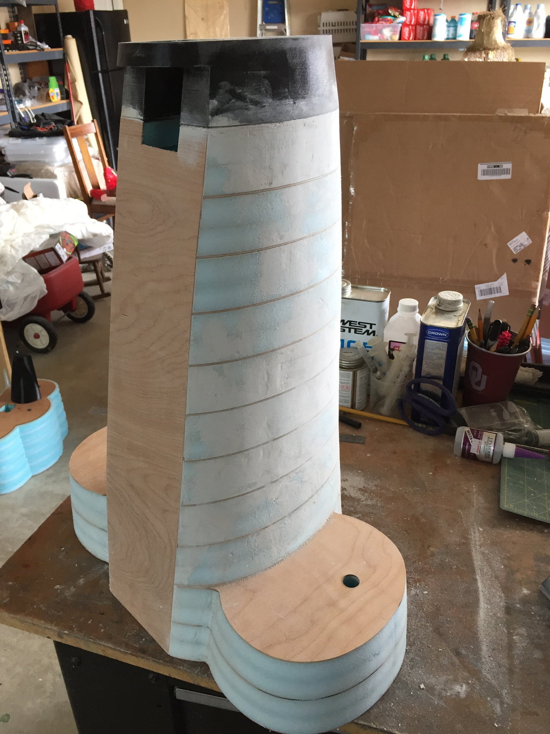
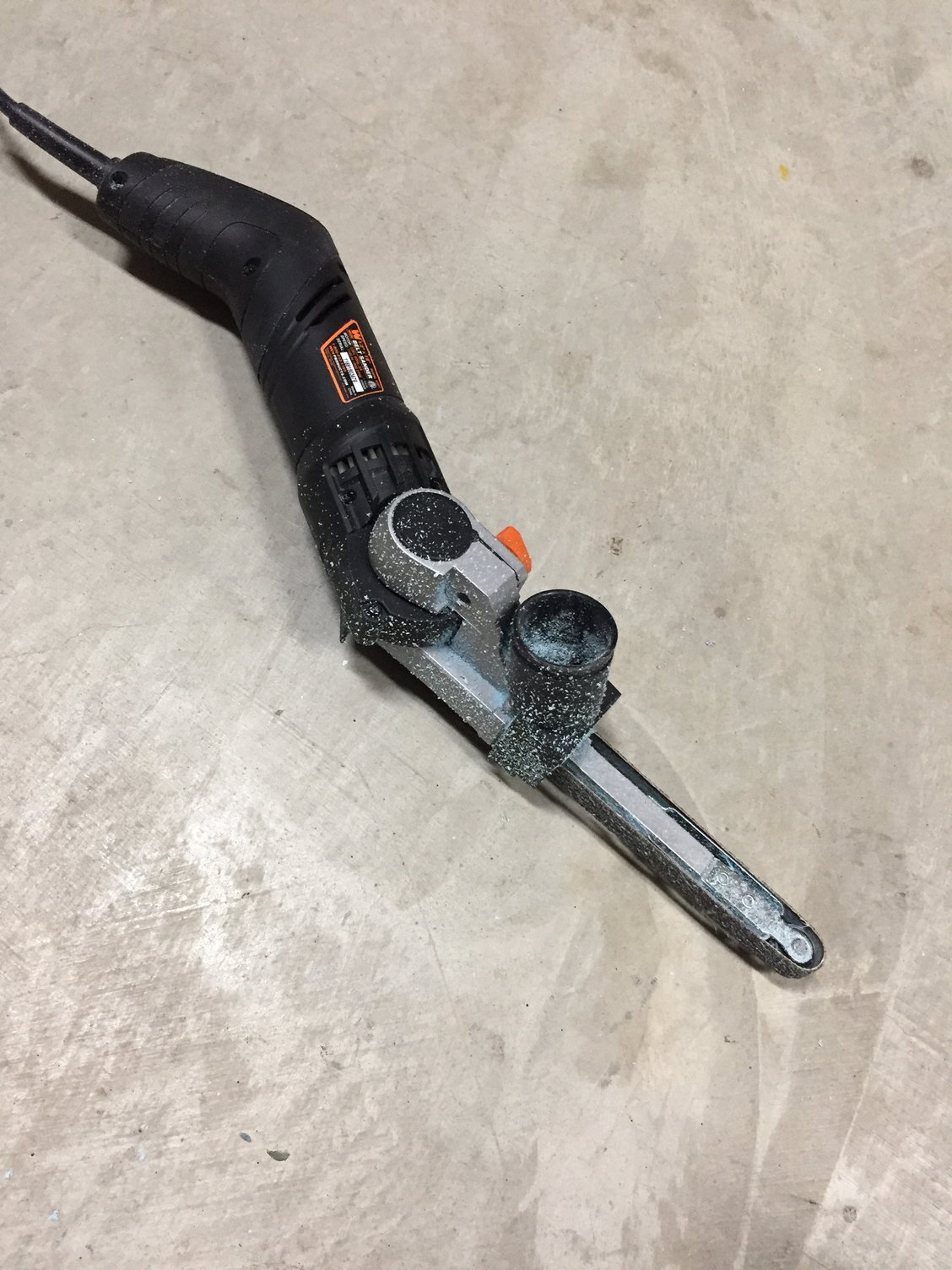
The foam was sanded using a hand-held power file/ belt sander, which made quick work of roughing out the shape down to the plywood. Hand sanding was then used for final shaping. Spackle was used to fill any defects before covering the entire surface with 6oz glass cloth to give a firm base for detail profiling, using Icing body filler. Once a smooth surface was achieved, a second layer of 6oz glass was applied, ready for final filling and primer.
Inlets will be molded separately, so false inlets were 3D printed and added with a recessed lip to facilitate bonding the inlet in place. A prominent bulged panel on the forward fuselage, along with the inlet bumps were 3D printed to match the underlying fuselage plug profile, resulting in minimal filler to blend them in.
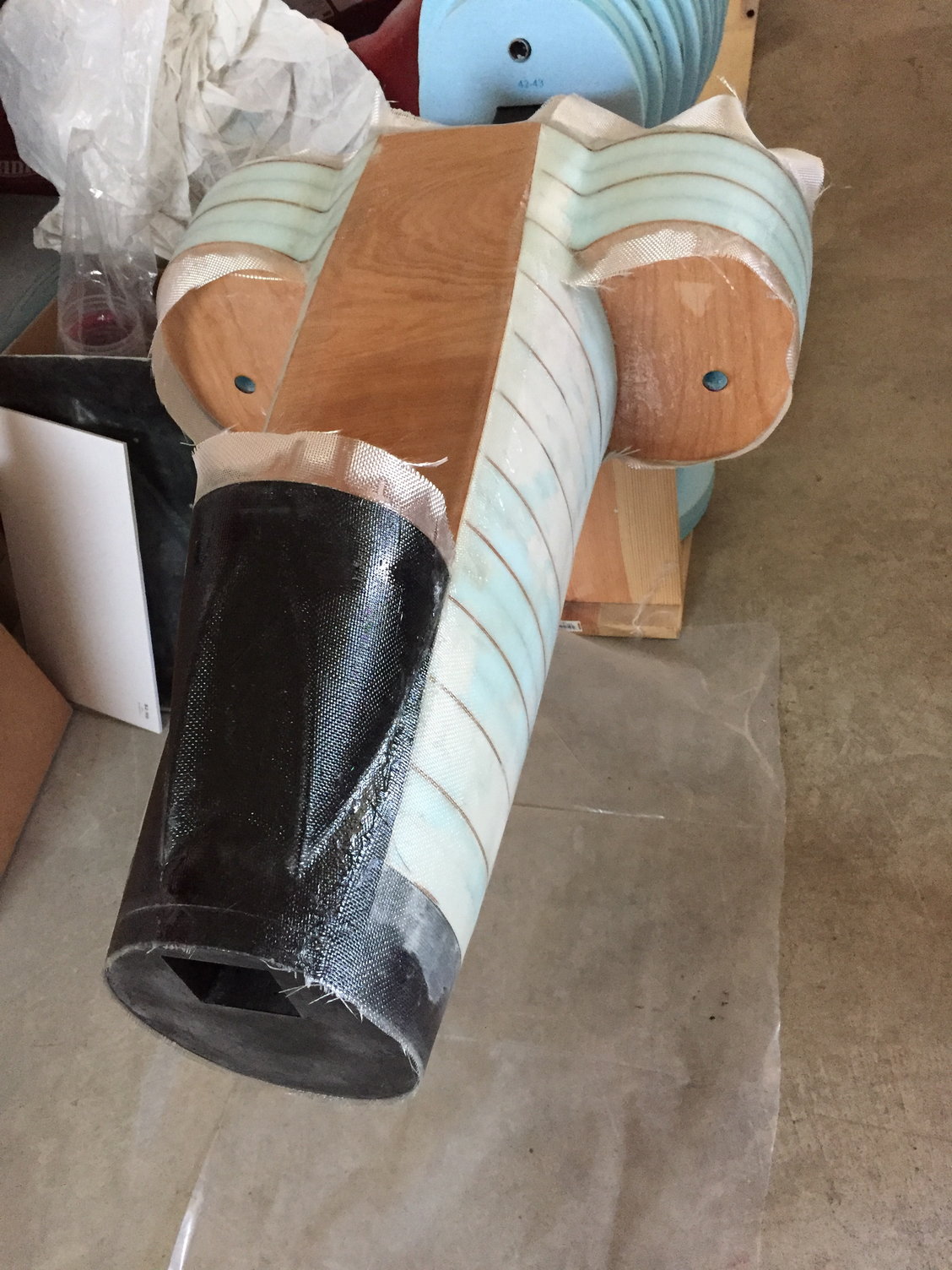

Inlets will be molded separately, so false inlets were 3D printed and added with a recessed lip to facilitate bonding the inlet in place. A prominent bulged panel on the forward fuselage, along with the inlet bumps were 3D printed to match the underlying fuselage plug profile, resulting in minimal filler to blend them in.
10-26-2018, 06:48 PM
#60
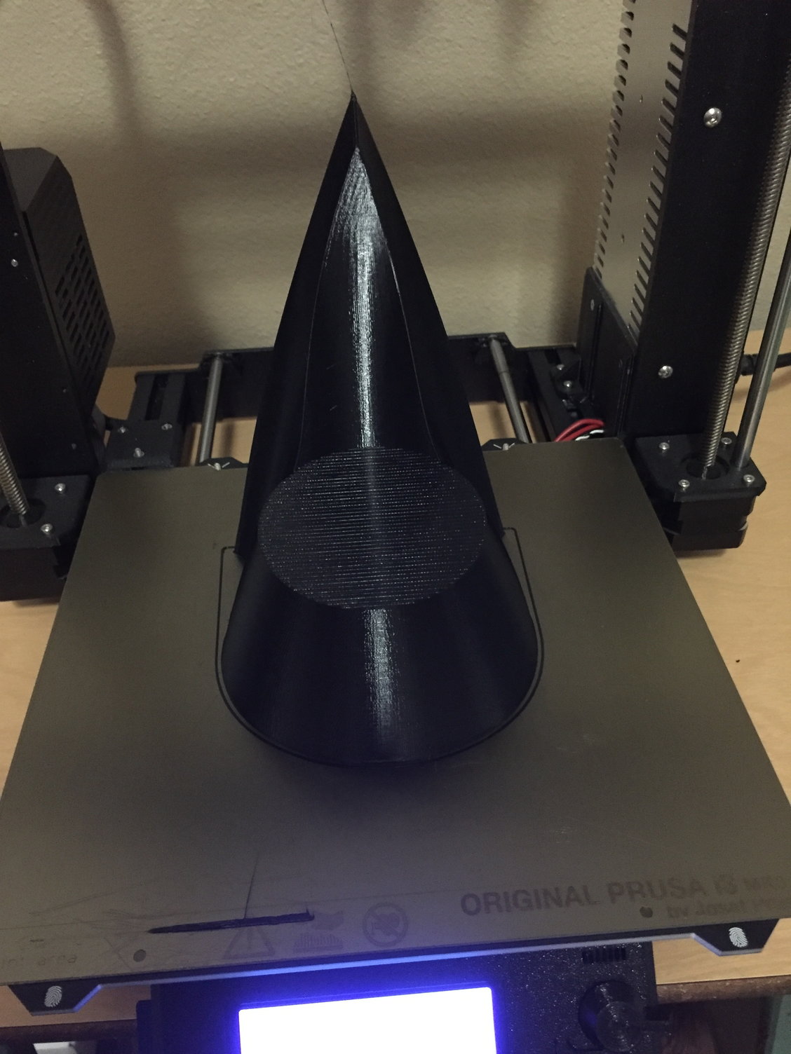
Next up was the radome.
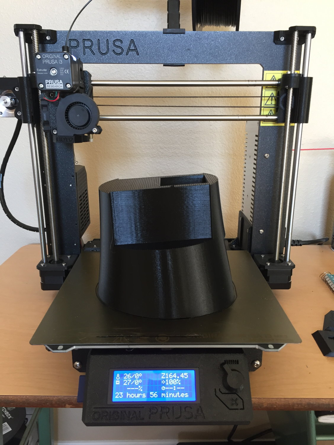
I 3D printed the radome and forward fuselage section that hinges open on the full scale with the cut line at the scale hinge line. I had to split the radome to reduce the height to fit the printer, but managed to nest both parts inside each other and print them simultaneously. I added some registration marks to ensure accurate alignment of the pieces. Print time was approx 48hrs.
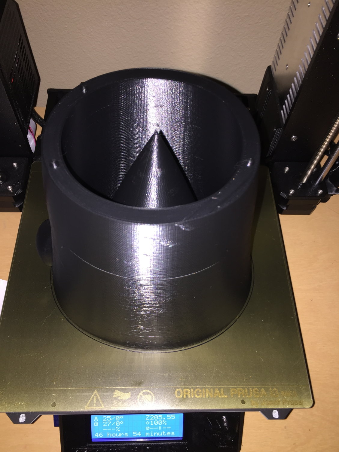
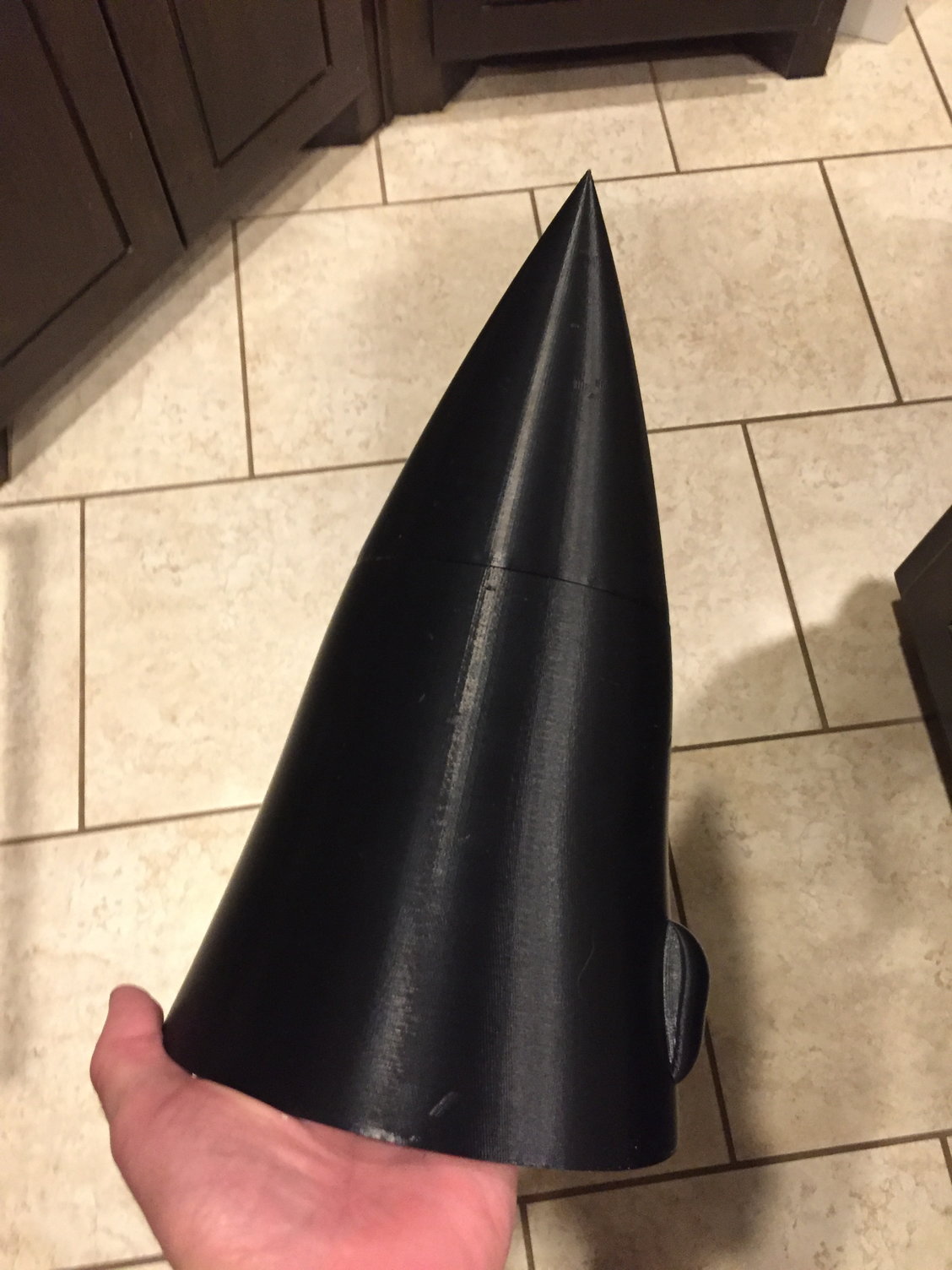
I 3D printed the radome and forward fuselage section that hinges open on the full scale with the cut line at the scale hinge line. I had to split the radome to reduce the height to fit the printer, but managed to nest both parts inside each other and print them simultaneously. I added some registration marks to ensure accurate alignment of the pieces. Print time was approx 48hrs.
10-26-2018, 06:55 PM
#61
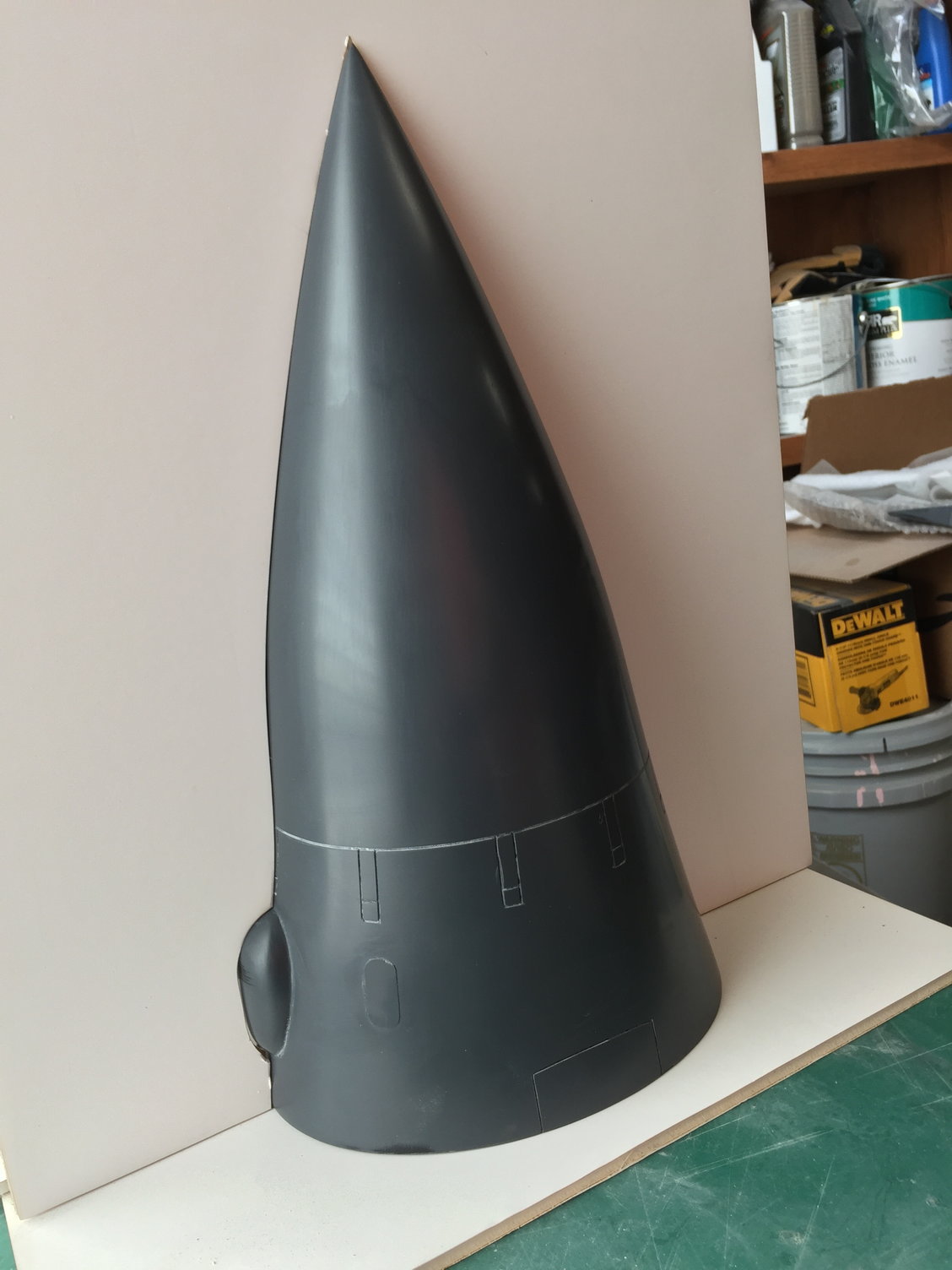
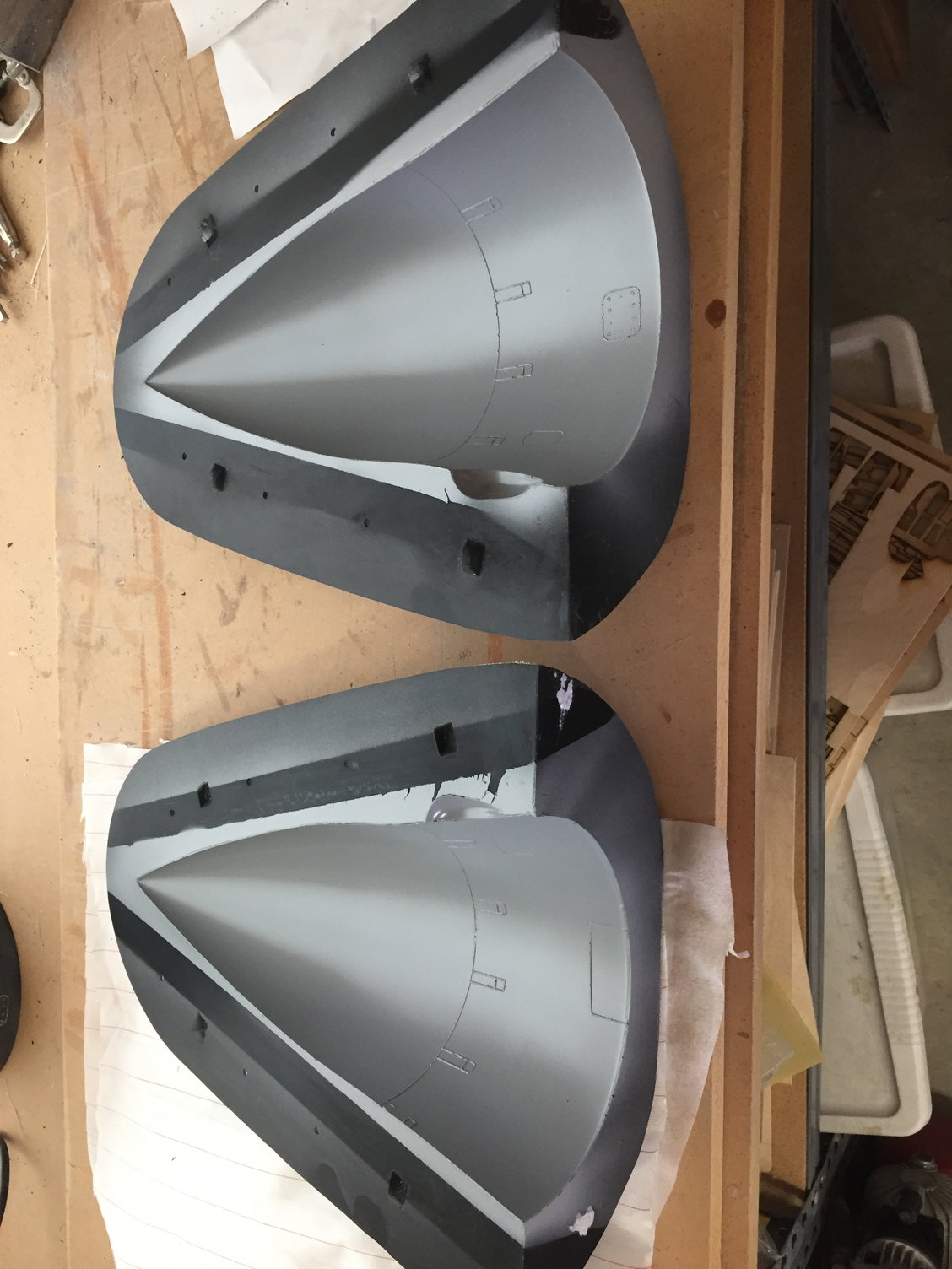
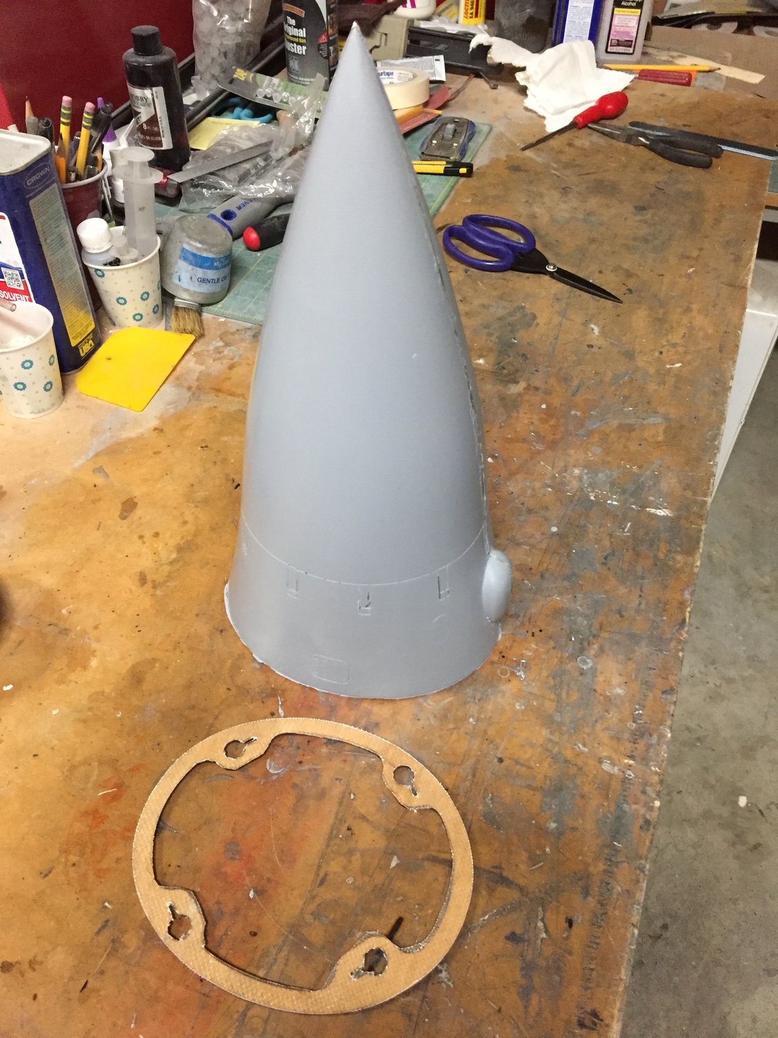
Once CA'd together, I finished the radome with Duratec and then engraved the surface detail and added the raised detail using a laser cut stencil as before.
The usual foam board was then used to make a parting plane and the molds laid up.
2 layers of 6oz glass were used to make the actual radome. For this part I tried KlassKote epoxy primer rather than car primer, and I was very impressed with the results. A much better bond between the primer and the epoxy layup. This will be my standard from now on.
I decided on using a key-way and large head screws to attach the radome to the fuselage with a 5deg twist locking it in place. The radome aft bulkhead with the keyways was laser cut from 5 ply and glassed on both sides before being epoxied into the radome.
Total radome finished weight was 5.5oz.
Last edited by JSF-TC; 10-26-2018 at 06:58 PM.
 10-27-2018, 05:48 AM
#63
Hi Reuben,
Thanks.
Neither. Just a very light sanding to ensure a keying surface and then 2-3 coats of Duratec Surfacing Primer. Sanded with 180, 400, 800 & 1200grit paper, then a rubbing compound to finish.
No need for any polish if using Frekote release agent.
Paul
Thanks.
Neither. Just a very light sanding to ensure a keying surface and then 2-3 coats of Duratec Surfacing Primer. Sanded with 180, 400, 800 & 1200grit paper, then a rubbing compound to finish.
No need for any polish if using Frekote release agent.
Paul
10-28-2018, 06:39 AM
#66
Gary,
Below are the steps I am currently using. It has evolved from my initial attempts and seems to work well.
The starting point is a finished plug mounted in a parting plane with all gaps sealed with a molding wax. I have been putting some registration bumps onto the parting plane using the molding wax so that the 2 halves align perfectly later.
Paul
Below are the steps I am currently using. It has evolved from my initial attempts and seems to work well.
The starting point is a finished plug mounted in a parting plane with all gaps sealed with a molding wax. I have been putting some registration bumps onto the parting plane using the molding wax so that the 2 halves align perfectly later.
- Apply Frekote 770-NC release agent. I have been spraying it and then immediately wiping it down with a shop rag soaked in Frekote to smooth it as it starts to evaporate. This helps avoid the fish-eye water marks that the basic sprayed Frekote tends to leave. Apply 3 coats with at least 20mins in between coats.
- Apply a tooling surface coat - https://store.acpsales.com/products/...ce-coat-et-01-
- The tooling surface coat is extremely thick so I use a plastic spreader to smooth it out over the plug and parting plane. I calculate the approximate surface area of the plug/ parting plane and assume a 1mm depth to determine the volume of tooling surface coat to mix up. Let cure.
- Build up at least 6 layers of 6-10oz heavy glass cloth over the entire mold surface. Looking for at least 1/16" total thickness, probably better erring towards 1/8". The surface coat is brittle and has no strength of its own so needs a rigid glass backing.
- When fully cured, remove the parting plane and clean up both plug and mold surfaces. Try not to remove the plug from the mold at this point. Re-apply Frekote to all areas.
- Use the same method to build up the second half of the mold.
- Once the second half is fully cured, before separating, drill through both mold flanges for a set of clamping bolts, at around 4-6" spacing. Clean up the mold edges and get rid of any sharp corners than could puncture the vacuum bag later. A hand-held grinder or Permagrit block works well.
- Moment of truth - separate the mold halves - Insert a wedge or similar at a joint and gently prize open. It will pop and crack but hopefully come free.
Paul
10-29-2018, 03:37 AM
#68
Gary,
I consider my plywood find a major triumph, both for quality and cost.
I was having trouble laser cutting the thicker (1/8") plywood and after a lot of research I found that the glue normally used to make plywood is not compatible with laser cutters. It just chars and absorbs the energy so you don't get a clean cut.
I eventually found a manufacturer of custom plywood that makes plywood using melamine glue which is laser compatible.
AIRCRAFT PLYWOOD MFG.
They can make the plywood from 1/16" up and in a wide range of wood types. They are MIL Spec rated and used on full size aircraft too, so great quality.
Initially I ordered a sheet of 1/8" all birch 5-ply and it was great. Cuts well on my laser cutter. Minimum order is a 4ft x 8ft sheet, but he will cut it down to 2ft x 4ft for shipping. I then take the 2ft x 4ft sheets to Lowes/ Home Depot and get them cut into 24" x 16" sheets to fit my laser cutter bed.
For the plug I ordered 1/16" 3-ply birch laser friendly (melamine) plywood. I think I used just over 4 4'x8' sheets for all the bulkheads.
The best thing about this supplier is that even though they are a custom ply manufacturer, the prices work out to be less than half what we normally pay, per square foot, from our usual 'hobby' suppliers.
I am phasing out all of my other plywood and migrating to these folks when I need more.
No hesitation for recommending this place for anyone that needs quality plywood.
Paul
Last edited by JSF-TC; 10-29-2018 at 07:57 AM.
10-29-2018, 06:16 PM
#70
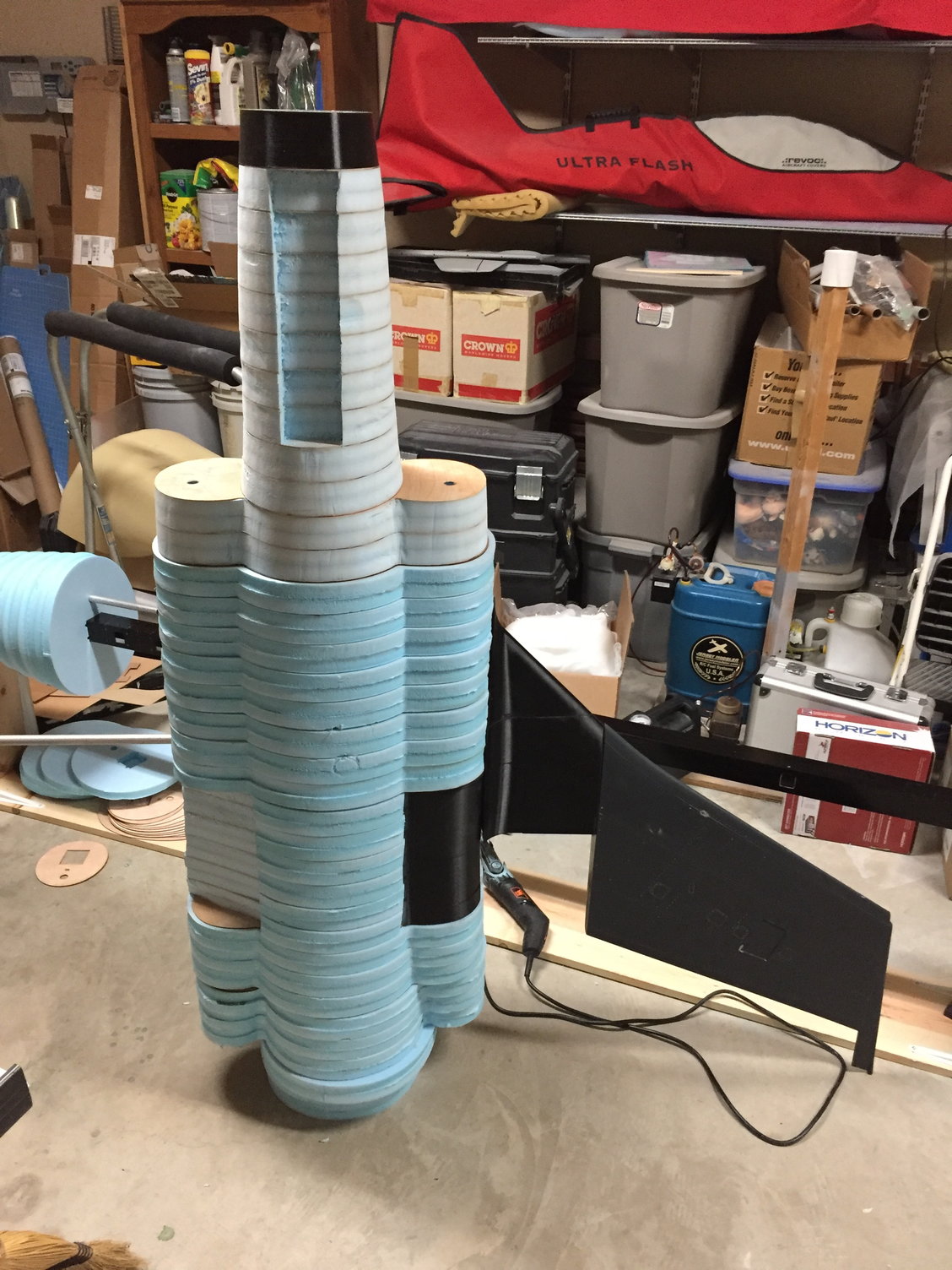
I've been continuing with the fuselage plug, gluing all the ply and foam sections together and sanding them down.
Finally got all the pieces assembled so took a motivational shot of the fuselage. Only about another 20inches for the rear fuselage closeout piece and speedbrake to add.

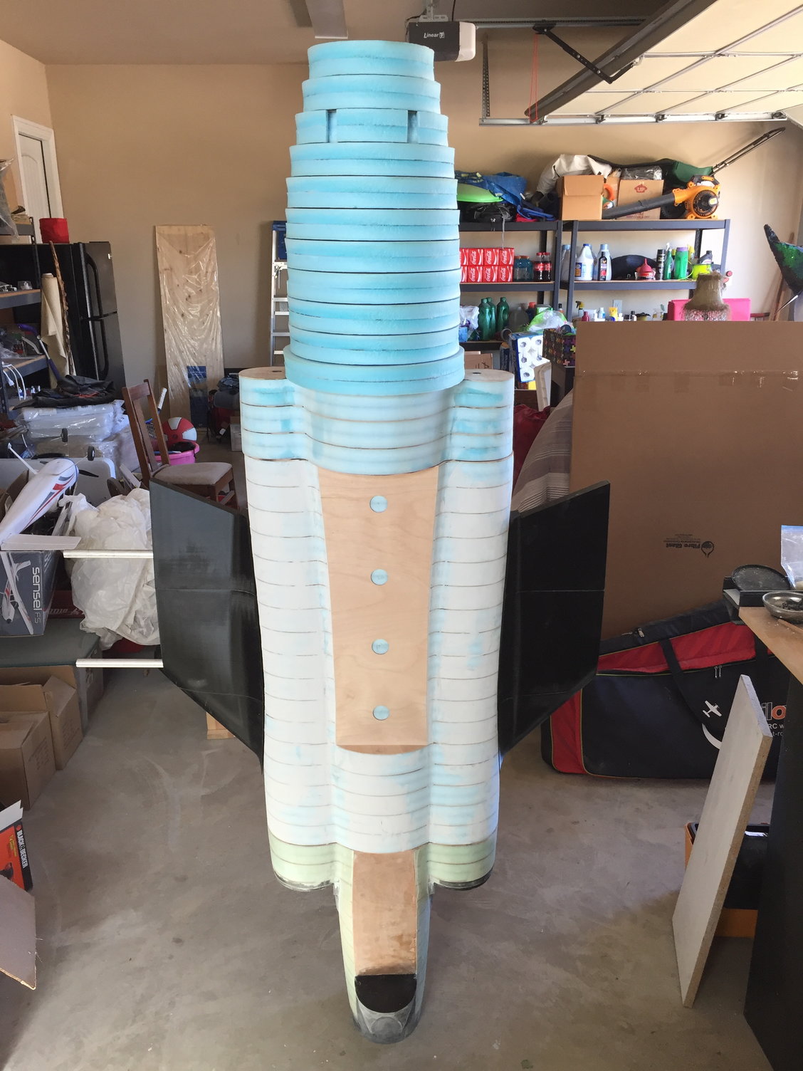
Finally got all the pieces assembled so took a motivational shot of the fuselage. Only about another 20inches for the rear fuselage closeout piece and speedbrake to add.

 10-29-2018, 06:24 PM
#73
Making the 2 part fuselage access hatch. The usual blue foam will be used between the ply formers. The front piece will slide into place and the rear part will have 2 spring loaded hatch catches. The same setup as on my DerJet Hunter which works well.
10-30-2018, 03:17 AM
#75
Not on me, but it is a Ten High 4060 50W with a 400mm x 600mm working area. Sold by Amazon.
Fairly basic and poor software, but I found a freeware software that is much better, K40 Whisperer
Ten High 4060 50W Laser Cutter
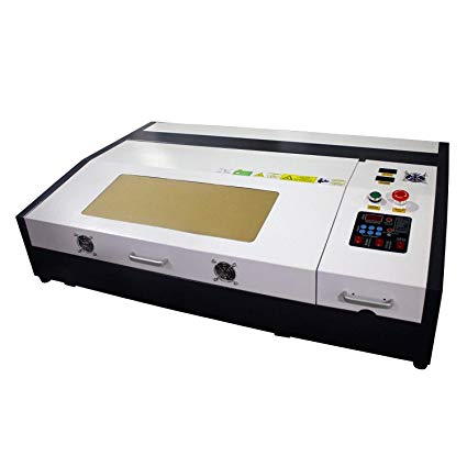
Fairly basic and poor software, but I found a freeware software that is much better, K40 Whisperer
Ten High 4060 50W Laser Cutter